
Thermal Mass Measurement
Uses thermal sensing technology for compatible gas-flow measurement.
Direct Mass Flow Measurement Using Thermal Sensing Technology
The FlowDo Thermal Mass Flow Meter uses thermal sensing technology to determine the mass flow of compatible gases. As gas moves across the sensing elements, it changes the transfer of heat from the heated sensor. The instrument processes this thermal response to determine the corresponding flow value.
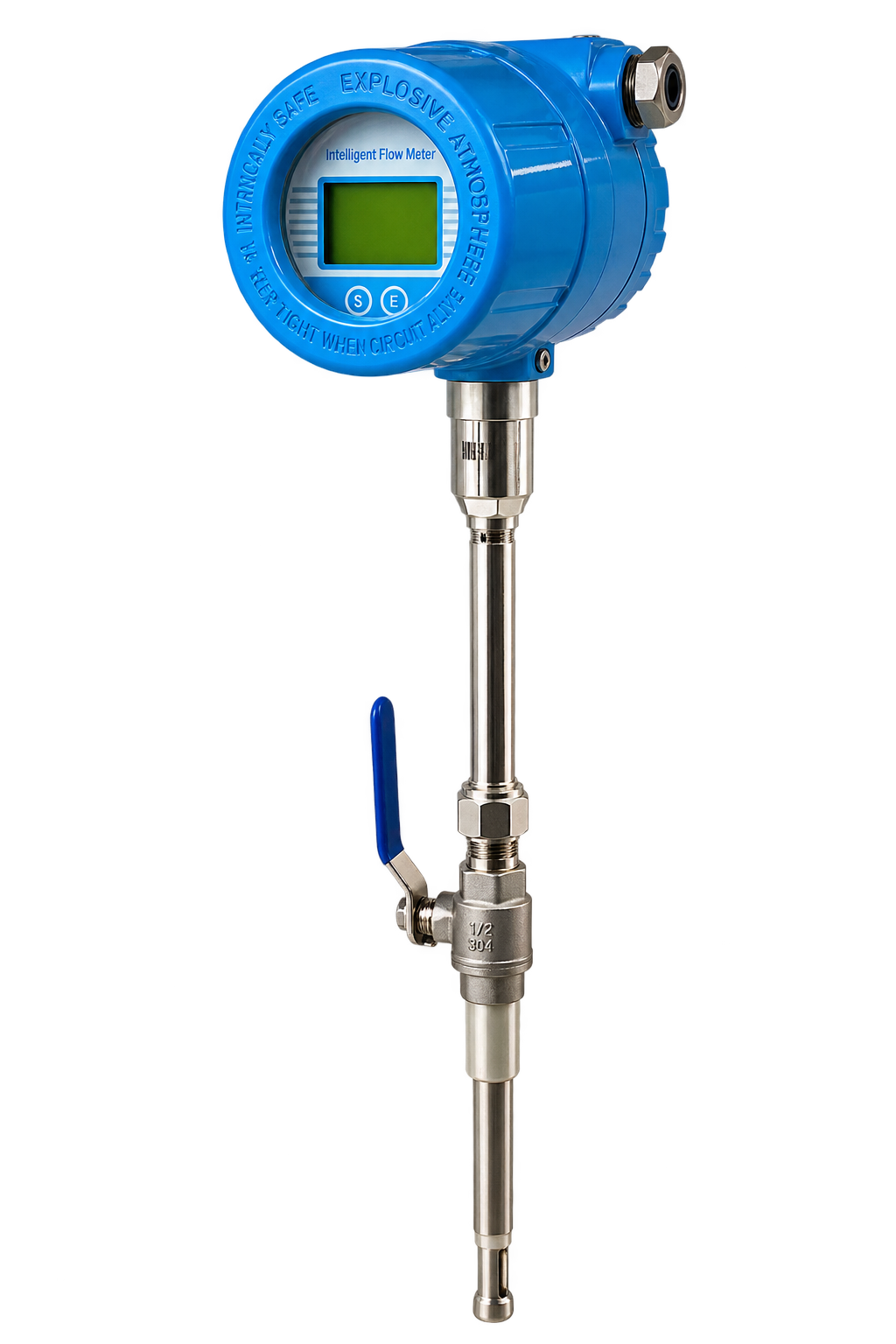
Direct gas mass-flow determination based on heat-transfer response across precision thermal sensing elements.
The FlowDo Thermal Mass Flow Meter is designed to measure the mass flow of compatible process gases using thermal sensing technology.
The sensing assembly typically monitors how flowing gas affects heat transfer around the measurement elements. As gas flow changes, the thermal response of the sensing system also changes.
The instrument electronics process this response using the applicable calibration to determine the corresponding mass-flow value.
Because the measurement is based on thermal interaction with the gas rather than a rotating turbine, the technology can provide direct gas-flow measurement without requiring a mechanical rotor.
Engineered for dependable, high-precision industrial gas flow measurement.
Uses thermal sensing technology for compatible gas-flow measurement.
The sensing system responds to heat transfer associated with flowing gas.
Measurement does not rely on a mechanical turbine rotor or moving bearing elements.
Provides continuous flow information within the supported operating range.
Applicable configurations provide local digital indication of rate and totalized flow.
Supported transmitter configurations provide signals for remote monitoring and automation.
Built with robust wetted materials suited for industrial process environments.
Meter selection and calibration are matched to the intended gas/application.
Engineered to deliver high measurement integrity across manufacturing and utility gas systems.
Designed to determine gas mass flow through thermal measurement without requiring external pressure/temperature compensation.
No rotating turbine measurement element is required, eliminating mechanical rotor wear, bearing friction and moving-part failures.
Suitable for compatible gas-flow applications according to calibration and configuration.
Provides continuous process-flow information for operational oversight and efficiency tracking.
Compatible outputs can integrate with industrial monitoring/control systems, PLCs and SCADA networks.
Minimal obstruction in the pipeline bore minimizes hydraulic pressure drops across the measuring point.
Technical specifications vary according to selected FlowDo Thermal Mass Flow Meter model and application parameters.
Engineering Notice: FlowDo manufactures and configures instruments for specific process criteria. Contact FlowDo technical sales to confirm exact specifications for your target gas, pressure, temperature, and pipe dimensions.
How varying gas velocity directly influences thermal dissipation from the measurement elements.
When gas velocity is low, fewer gas molecules pass the heated sensor per second. Heat dissipation into the gas stream is relatively small:
As gas velocity increases across the sensing element, the rate of convective heat transfer increases significantly:
Differential thermal sensing combining process temperature compensation with active flow sensing.
Measures the actual process temperature of the passing gas. This measurement provides the dynamic temperature baseline required for accurate thermal comparison.
Maintained at a controlled thermal condition above process temperature. Heat carried away by the passing gas represents the gas mass-flow rate.
Thermal mass-flow instruments commonly use temperature-sensitive elements to establish process-gas temperature and thermal response. The exact sensing architecture depends on the selected FlowDo model.
Why direct mass measurement provides substantial engineering advantages in compressible gas systems.
Measures the actual quantity of mass passing through the system per unit time. Because mass is conserved regardless of pressure or temperature variations, mass flow directly quantifies the true substance flow.
Measures the physical volume of fluid passing per unit time. For compressible gases, actual volume varies continuously with fluctuating process pressure and temperature.
Gas-flow instruments frequently standardize gas volumetric flow to common baselines such as Normal cubic meters per hour (Nm³/h) or Standard cubic meters per hour (Sm³/h). Direct thermal mass measurement allows seamless conversion to standardized volumetric rates without requiring separate external temperature and pressure transmitters when reference conditions are pre-defined.
Different gases have different thermal properties. A Thermal Mass Flow Meter must therefore be selected and calibrated for the intended gas or gas mixture.
Specific heat capacity (Cp), thermal conductivity, and dynamic viscosity vary widely between gases. The sensor response is intrinsically linked to these specific thermodynamic attributes.
During instrument manufacturing, the transmitter electronics are programmed with characteristic conversion curves tailored to the designated gas calibration:
Mounting options designed to match pipeline sizing, pressure limits, and operational retrofitting constraints.
An insertion configuration positions the thermal sensing probe within the process pipe. Correct insertion depth and orientation are important for reliable measurement.
Inline configurations incorporate the thermal sensing section within a dedicated meter body installed directly in the pipeline.
The thermal sensing elements should be positioned according to the installation requirements of the selected FlowDo meter so that they are properly exposed to the process flow.
The sensing element must be positioned correctly within the pipe's flow profile. Required insertion depth depends on meter design, pipe size and installation arrangement.
Flow disturbances caused by elbows, valves, reducers, pumps and other components can affect the velocity profile. Follow the upstream/downstream installation requirements specified for the selected FlowDo Thermal Mass Flow Meter.
Core process factors that determine the mechanical and electronic sizing of thermal mass meters.
For insertion Thermal Mass Flow Meters, pipe dimensions are required to convert the measured velocity/mass-flow response into the applicable process-flow value according to the instrument configuration.
The selected sensor, probe assembly and process connection must be suitable for the process operating/design pressure. Pressure can also influence actual volumetric gas flow and gas density.
The sensing probe and electronics must be suitable for the actual gas temperature and ambient operating conditions: Process Gas Temperature + Ambient Temperature → Select Correct Meter Configuration.
Provide minimum, normal and maximum expected flow when selecting the meter. This helps ensure the application remains within the selected instrument's supported measurement range.
Industrial gas applications benefiting from dedicated thermal mass flow monitoring.
Monitoring compressed-air consumption and distribution provides essential visibility into industrial plant operating costs and pneumatic system efficiency.
Direct thermal mass measurement in main compressor headers, distribution risers, and machine feed lines delivers continuous flow and totalized consumption figures. Flow data can support compressed-air leak and consumption analysis.
Biogas composition can vary, and thermal properties depend on the gas mixture. Product selection should therefore consider the expected composition (CH4, CO2), moisture, contaminants, pressure, temperature and flow range.
Evaluating process gas conditions, moisture, and composition stability prior to instrument selection.
Liquid droplets or condensation contacting a thermal sensing element can alter heat-transfer behavior and may affect measurement depending on the sensor design: Dry/suitable gas supports stable measurement, while condensation requires application review.
If the process-gas composition changes significantly from the calibration basis, measurement performance may be affected because the thermodynamic properties deviate from the programmed conversion table.
Thermal mass meters perform reliably with non-condensing, particulate-free compatible gases. Applications with heavy coatings, sticky particulates or wet vapor streams require review by FlowDo application engineers.
Selecting the optimal measurement principle for your industrial fluid, pipe, and accuracy requirements.
Thermal mass meters measure gas mass flow without moving parts, whereas turbine meters determine liquid velocity using mechanical rotor rotation.
View Turbine Flow Meter →Thermal mass meters specialize in direct gas mass flow, while vortex meters measure volumetric flow across steam, gas, and liquid using stationary bluff bodies.
View Vortex Flow Meter →Thermal mass meters monitor heat transfer in gas streams; ultrasonic meters monitor acoustic sound waves across filled liquid pipes.
View Ultrasonic Flow Meter →Thermal mass meters measure compatible gases with no conductivity requirement; electromagnetic meters require electrically conductive liquids.
View Electromagnetic Flow Meter →| Measurement Attribute | Thermal Mass Flow Meter (This Product) | Electromagnetic Flow Meter | Turbine Flow Meter | Vortex Flow Meter | Ultrasonic Flow Meter |
|---|---|---|---|---|---|
| Measurement Principle | Thermal convective heat transfer | Electromagnetic induction | Flow-driven rotor rotation | Vortex shedding (Kármán street) | Sound waves (transit time) |
| Primary Measured Medium | Compatible industrial gases | Conductive liquids | Clean low-viscosity liquids | Steam, gas, liquid | Acoustic clean liquids |
| Primary Measurement Output | Direct Mass Flow (kg/h, Nm³/h) | Volumetric Flow (m³/h, L/min) | Volumetric Flow (m³/h, L/min) | Volumetric / Mass Flow | Volumetric Flow (m³/h, L/min) |
| Moving Mechanical Parts | No moving parts | No moving parts | Yes (rotor & bearings) | No moving parts | No moving parts |
| Conductivity Required? | No conductivity required | Yes (≥ 5 μS/cm) | No conductivity required | No conductivity required | No conductivity required |
| Mounting Configuration | Insertion probe or inline spool | Inline flanged / wafer | Inline flanged / threaded | Inline flanged / wafer | Clamp-on or inline spool |
| Added Pipeline Pressure Drop | Negligible to very low | Zero (unobstructed bore) | Low to moderate across rotor | Low to moderate across bluff body | Zero for clamp-on |
| Primary Selection Focus | Gas composition, pipe size, flow range | Fluid conductivity, liner compatibility | Fluid cleanliness, viscosity | Minimum velocity threshold, vibration | Acoustic transmission, wall thickness |
Selection depends on process medium, pipe conditions, flow range, pressure, temperature, installation access and required measurement performance.
Converting sensor heat-transfer responses into plant control signals, PLC inputs, and remote cloud dashboards.
Provide key pipeline and gas parameters to identify a suitable FlowDo Thermal Mass Flow Meter configuration.
Specify the exact process gas to be measured (e.g., Compressed Air, Nitrogen, Biogas, or specified process gas).
Indicate whether the gas is pure or a multi-component mixture with expected percentage breakdown.
Provide pipeline internal/external diameter, pipe schedule, and material specification.
Minimum expected process gas flow rate during low-demand or baseline periods.
Nominal operating gas flow rate under typical continuous operational conditions.
Maximum anticipated peak gas demand or upset-condition capacity.
Required engineering rate and totalizer units (e.g., Nm³/h, kg/h, Sm³/h, or SCFM).
Normal operating pipeline pressure and maximum design pressure rating.
Normal and maximum gas temperature inside the pipeline stream.
Environmental ambient temperature range at the transmitter installation location.
Select between Insertion probe mounting or Inline spool-body configuration.
Flanged, threaded, or hot-tap valve connection matching piping standards.
Required control signal (e.g., 4–20 mA analog, pulse, or frequency).
Industrial bus protocol if digital networking is required (e.g., RS485 Modbus RTU or HART).
Integrated transmitter digital display for rate and totalized volume indication.
Specify whether integrated forward totalization or batch volume is required.
Explore complementary FlowDo industrial flow and process instrumentation.
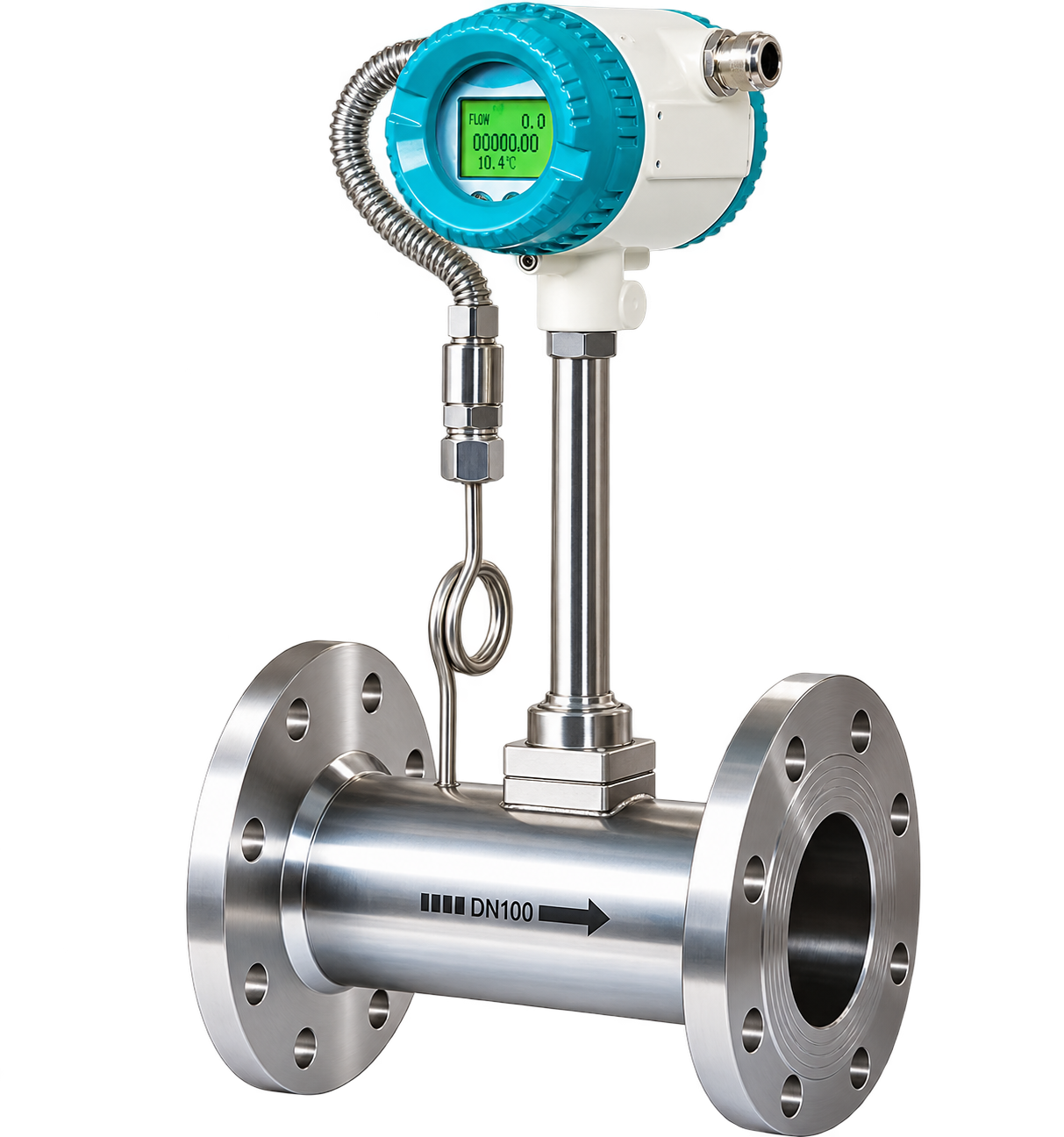
Industrial vortex flow meter using vortex-shedding technology for compatible steam, gas, and liquid process-flow applications.
View details & specs →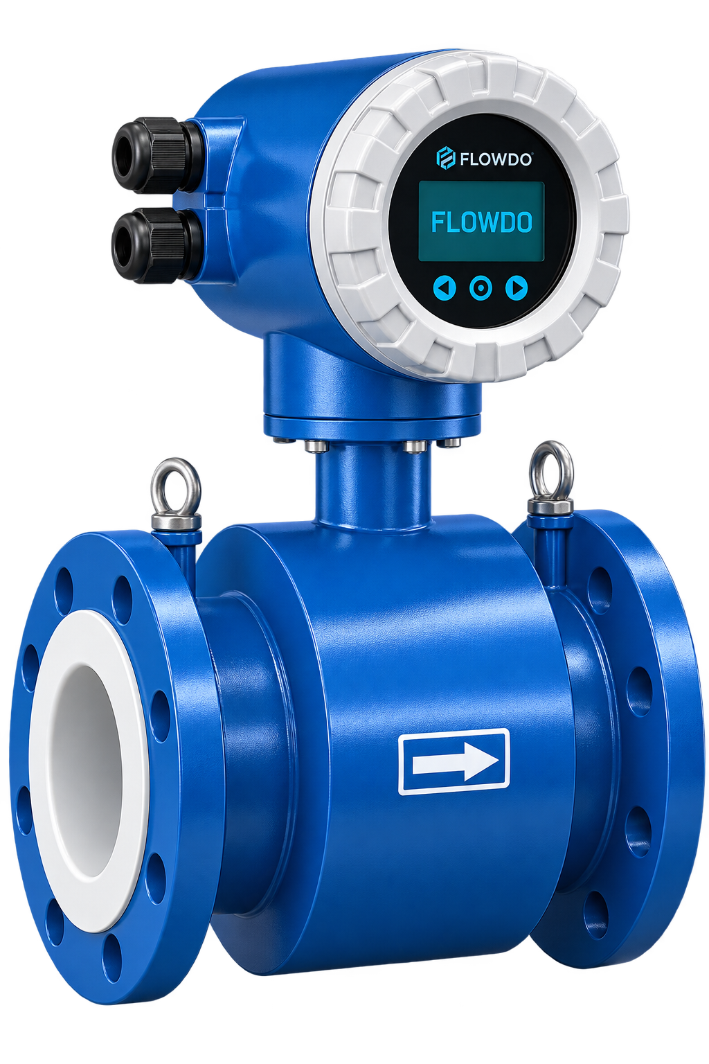
Industrial ultrasonic flow meter for non-intrusive and inline transit-time pipeline flow measurement.
View details & specs →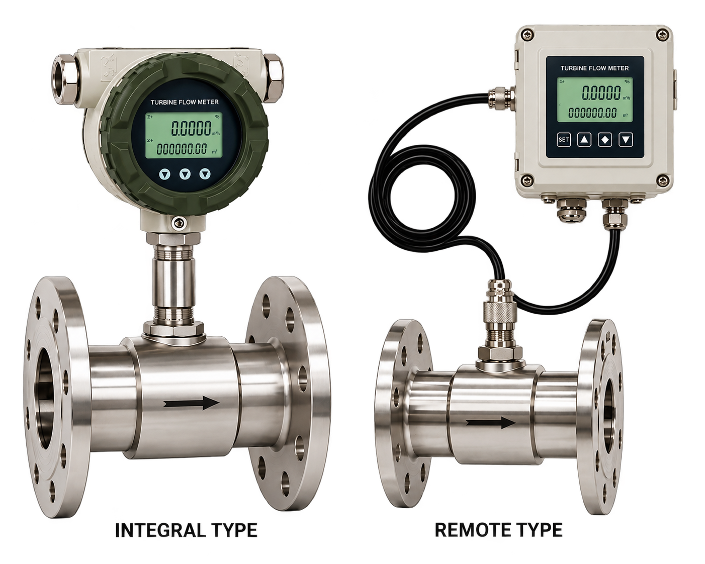
High-precision rotor rotation flow meter for clean, low-viscosity liquid measurement and batching.
View details & specs →
Full-bore electromagnetic induction flow meter for conductive liquids, water, wastewater, and slurries.
View details & specs →Technical guidance and answers for common industrial gas mass-flow questions.
A Thermal Mass Flow Meter measures the mass flow of compatible gases by monitoring heat-transfer behavior around thermal sensing elements.
Gas flowing across the sensing element changes the rate of heat transfer. The transmitter processes this thermal response using the applicable calibration to determine mass flow.
No. Thermal mass-flow measurement does not require a rotating turbine measurement element.
Mass flow represents the amount of mass passing through the system per unit time.
No. Mass flow measures mass per unit time, while volumetric flow measures volume per unit time.
Different gases have different thermal properties, so the meter's calibration and configuration should correspond to the intended process gas.
Compressed-air measurement should only be advertised where confirmed for the selected FlowDo configuration.
Biogas applications require review of gas composition, moisture, contaminants, pressure, temperature and flow range.
Oxygen service requires appropriate materials, cleanliness and product suitability. It should only be advertised when the selected FlowDo meter is specifically approved/configured for the application.
Process pressure should be included during meter selection. Actual volumetric gas properties vary with pressure, while the thermal mass-flow measurement architecture is based on gas thermal response and calibration.
Yes. Both process-gas and ambient temperature must remain within the limits of the selected meter.
Yes. Significant changes in gas composition can alter thermal properties and affect measurement response.
Wet-gas or condensation conditions require application review because liquid droplets can affect the thermal sensor.
An insertion meter places the sensing probe into the process pipe to measure gas-flow conditions.
An inline configuration integrates the sensing section into a dedicated meter body installed in the pipeline.
4–20 mA should only be shown where the selected FlowDo configuration confirms it.
Modbus or other digital communication should only be advertised where confirmed.
Yes, where the selected meter's output/interface is compatible with the automation system.
FlowDo IoT integration should only be shown where a compatible telemetry/interface architecture is available.
Provide gas type/composition, pipe size, minimum/normal/maximum flow, pressure, temperature, installation type and required output.
Share your gas type, gas composition, pipe size, minimum/normal/maximum flow, pressure, temperature, installation requirement and required output with FlowDo to identify a suitable Thermal Mass Flow Meter configuration.
For faster selection, provide: Gas Type • Gas Composition • Pipe Size • Minimum Flow • Normal Flow • Maximum Flow • Process Pressure • Process Temperature • Installation Type • Process Connection • Required Output