
Precision Industrial Instrumentation Ahmedabad, Gujarat • India
Home / Products / Flow Meters / Electromagnetic Flow Meter
Flow Meters

Electromagnetic Flow Meter

Accurate Flow Measurement for Conductive Liquids Without Moving Parts

Reliable Flow Measurement for Conductive Liquids

The FlowDo Electromagnetic Flow Meter measures volumetric flow using electromagnetic induction. Designed for compatible electrically conductive liquids, it provides reliable process-flow measurement without mechanical moving parts in the measuring tube.
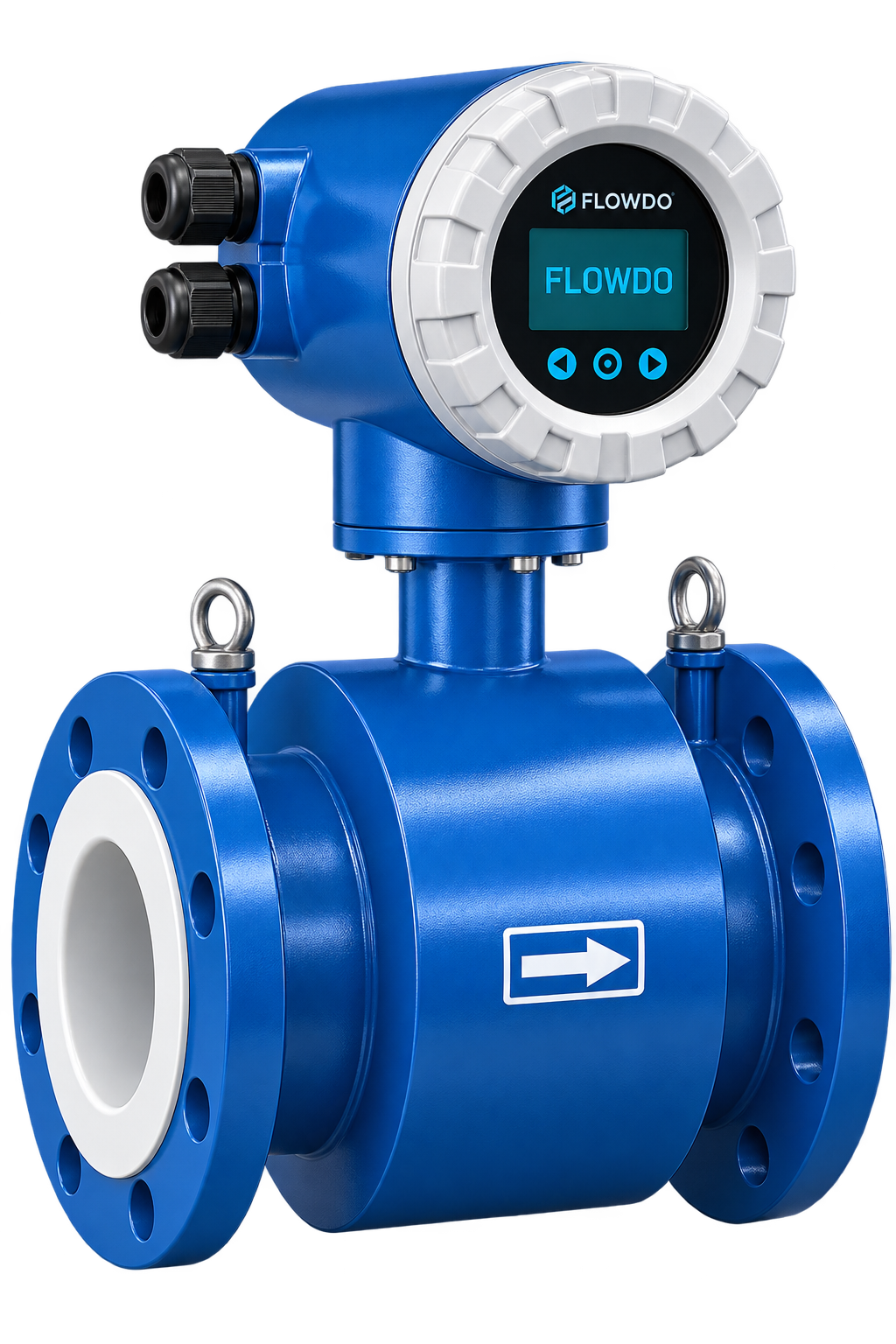
FlowDo Electromagnetic Flow Meter for industrial conductive liquid flow measurement
ELECTROMAGNETIC Principle
VOLUMETRIC FLOW Measurement
NO MOVING PARTS Flow Path
CONDUCTIVE LIQUIDS Application
Product Overview

Electromagnetic Flow Measurement for Industrial Processes

The FlowDo Electromagnetic Flow Meter is designed to measure the volumetric flow rate of compatible electrically conductive liquids.

During operation, the fluid passes through a magnetic field generated across the measuring tube. As the conductive liquid moves through this field, a small electrical voltage is induced. Electrodes positioned in the measuring section detect this signal, and the transmitter electronics convert it into a corresponding flow value.

Because the measurement principle does not require mechanical moving elements in the flow path, electromagnetic flow measurement is well suited to many water, wastewater and industrial process applications.

Selection Guidance: Final meter selection should consider pipe size, flow rate, fluid conductivity, liner and electrode compatibility, temperature, pressure, process connection, output and installation conditions.

Key Engineering Highlights

  • Non-intrusive electromagnetic volumetric flow sensing principle
  • Completely unobstructed lined measuring tube with zero mechanical rotating parts
  • Digital transmitter display for instantaneous rate and accumulated volume indication
  • Standard 4–20 mA current output and compatible industrial automation interfaces
  • Liner and electrode materials selected according to chemical and thermal compatibility
  • Rugged flanged process connection engineered for demanding industrial pipelines
FLOWDO • MAG 148.5 m³/h • FLOW
Integrated Front Digital Indication & Pushbutton Keys
Direct Reading Instantaneous Flow Indication

High-contrast digital readout displays the instantaneous volumetric flow rate on-site in configurable engineering units.

Accumulation Configurable Flow Totalization

Applicable converter configurations record cumulative fluid volume over time for operational tracking and water accounting.

Signal Output Standard 4–20 mA DC Output

Transmits a calibrated proportional analog current signal for seamless integration with PLCs, panel indicators, and DCS systems.

Instrumentation Capabilities

Key Features

Engineered for dependable, high-accuracy industrial liquid metering.

Electromagnetic Measurement

Uses electromagnetic induction for volumetric flow measurement of compatible conductive liquids.

No Moving Flow Elements

Measurement does not rely on mechanical rotating components in the measuring tube.

📈

Continuous Flow Monitoring

Provides continuous volumetric-flow information with rapid dynamic response to flow variations.

🖥

Local Digital Display

Integrated front display delivers clear local reading of instantaneous flow and total volume.

Configurable Totalization

Tracks cumulative volume for batch verification, daily consumption, and billing management.

Process Signal Outputs

Standard 4–20 mA current loop and configurable digital outputs for automation integration.

🛡

Robust Industrial Housing

Built for industrial field conditions with high-grade protective enclosures and flanged connections.

Bidirectional Flow Sensing

Supported transmitter configurations accommodate forward and reverse flow direction tracking.

Operational Advantages

Built for Reliable Industrial Flow Measurement

Delivering measurable performance improvements for plant operators and instrumentation engineers.

01 — Flow Channel

Unobstructed Bore

The unobstructed measuring tube minimizes pressure drop and avoids mechanical rotor clogging.

02 — Maintenance

Low Mechanical Wear

Without internal rotating parts, mechanical wear is minimized compared with mechanical velocity meters.

03 — Local Visibility

Direct Process Indication

The integrated digital display allows operating personnel to check instantaneous flow and total volume locally.

04 — Automation

Standard Process Output

Standard 4–20 mA transmission facilitates straightforward integration with existing control loops and indicators.

05 — Medium Suitability

Material Configuration

Available liner and electrode configurations can be selected according to supported process requirements.

06 — Plant Connectivity

Automation Integration

Compatible transmitter outputs can integrate with PLC and SCADA architectures for process automation.

Technical Configuration

Product Specifications

Comprehensive technical specification architecture for FlowDo Electromagnetic Flow Meters.

Brand / Manufacturer FlowDo
Product Name FlowDo Electromagnetic Flow Meter
Primary Category Flow Meters
Product Type Industrial Electromagnetic Flow Meter
Measured Parameter Volumetric Flow Rate
Measurement Principle Electromagnetic Induction (Faraday’s Law)
Nominal Diameter / Line Size According to selected model / pipeline requirements
Flow Range According to selected size and application
Velocity Range According to selected model
Accuracy According to selected model
Repeatability According to selected model
Bidirectional Measurement Available as per transmitter configuration
Minimum Conductivity Requirement According to selected model and application
Empty-Pipe Detection Available on selected FlowDo transmitter configurations
Display Type Integrated Digital Display (standard compact configuration)
Instantaneous Flow Indication Supported on digital display
Flow Totalization Supported on configurable transmitter configurations
Configurable Display Units Configurable as per selected transmitter model (e.g. m³/h, LPM, etc.)
Display Backlight Supported on digital display
Analog Output 4–20 mA DC
Pulse / Frequency Output Available as per transmitter configuration
Relay Output Available on selected transmitter configurations
Digital Communication RS485 / Modbus RTU / HART (configuration dependent)
Power Supply According to selected configuration (e.g. 230 VAC / 24 VDC options)
Power Consumption Model dependent
Cable Entry Standard industrial conduit entries
Electrical Connection Screw terminals inside transmitter junction housing
Liner Material Selected according to process-medium compatibility
Electrode Material Selected according to process-medium compatibility
Measuring Tube Stainless steel measuring section with non-conductive liner
Sensor Body Material Industrial coated carbon steel / stainless steel (model dependent)
Flange Material Carbon steel / Stainless steel (model dependent)
Grounding Arrangement Grounding electrode / grounding rings (application dependent)
Process Connection Flanged (standard) / other supported configuration
Flange Standard According to selected standard (e.g. ANSI / DIN / JIS / BS)
Pressure Rating According to selected model / flange rating
Process Temperature Model / material dependent
Ambient Temperature According to selected transmitter model
Enclosure Protection Rating According to selected model (e.g. IP65 / IP67 / IP68 options)
Process Fluid Electrically conductive liquids according to material/application compatibility
Primary Application Industrial Liquid Flow Measurement
Final Technical Specifications Note: Final specifications depend on the selected FlowDo Electromagnetic Flow Meter model, line size, and process application. For correct engineering selection, provide pipe size, flow range, process liquid, conductivity, temperature, pressure, process connection, and required output.
Application Engineering

Designed for Electrically Conductive Liquids

The electromagnetic measurement principle requires the process liquid to provide sufficient electrical conductivity for the electrodes to detect the induced signal.

SUITABLE CONCEPTUALLY

Conductive Liquid Medium

When an electrically conductive fluid flows through the field, continuous charge separation creates a clean electrical signal across the electrodes:

Conductive Liquid → Stable Induced Potential → Precise Flow Measurement
  • Raw water, potable water, and municipal water supplies
  • Industrial wastewater, sewage, and effluent streams
  • Compatible aqueous chemical solutions and acids/alkalis
  • Cooling tower circulating water and process utilities
NOT SUITABLE CONCEPTUALLY

Non-Conductive Media

Fluids without sufficient electrical conductivity cannot generate an induced signal detectable by standard measuring electrodes:

Non-Conductive Liquid → Insufficient Electrode Signal → Alternative Technology Required
  • Hydrocarbons, diesel, petrol, and refined fuels
  • Lubricating oils, hydraulic fluids, and mineral oils
  • Industrial gases, compressed air, and steam
  • Ultra-pure demineralized water with zero ion content
Conductivity Notice: Minimum conductivity requirements depend on the selected FlowDo meter and transmitter configuration. Always review fluid properties during model selection.
Flow Path Design

No Mechanical Moving Parts in the Measuring Tube

Electromagnetic flow measurement does not rely on a turbine, paddle or other mechanical rotor in the flow path.

The liquid passes cleanly through a smooth lined measuring tube while the external magnetic field and flush electrodes perform the measurement without protruding into the fluid stream.

Unlike mechanical velocity meters, there are no rotating rotors, bearings, or pivots subjected to wear, bearing seizure, or fiber entwinement.

No Mechanical Rotor Zero moving parts in the liquid flow channel.
Minimal Flow Obstruction Negligible hydraulic pressure loss across the meter body.

Engineering Advantages

  • Eliminates mechanical rotor wear and bearing maintenance
  • Suitable for compatible liquids containing suspended solids depending on liner/electrode selection
  • Bi-directional measurement capability on supported transmitter architectures
  • Unrestricted bore profile preserves pumping energy and pipeline pressure
Meter Construction

Inside an Electromagnetic Flow Meter

Key functional components comprising the sensor body and converter assembly.

01
Transmitter / Converter

Housed in a rugged enclosure, converts induced microvolt electrode signals into flow values and process outputs.

02
Digital Display

Clear front digital display for instantaneous flow rate and configurable flow totalization indication.

03
Measuring Tube

Non-magnetic tube providing an unobstructed passage for the process fluid.

04
Magnetic Coils

Electromagnetic field coils positioned above and below the tube to generate the measurement magnetic field.

05
Insulating Liner

Isolates the metallic tube and prevents short-circuiting of the induced signal across the pipe wall.

06
Measuring Electrodes

Positioned flush in the measuring section to detect the induced potential difference in the flowing liquid.

07
Process Flanges

Heavy-duty bolted flanges on both ends engineered to connect seamlessly to industrial process piping.

08
Grounding Arrangement

Provides an electrical reference between the process liquid and transmitter circuitry for signal stability.

Materials Engineering

Liner and Electrode Material Selection

Selecting wetted components around process chemistry, temperature, and operating conditions.

Wetted Boundary

Select the Liner for the Process Medium

The liner isolates the measuring tube from the process liquid and should be selected according to chemical compatibility, temperature, abrasion and process conditions.

Liner Selection Factor: Available liner materials depend on the selected FlowDo model and process compatibility. Share fluid type, operating temperature, and potential abrasive content for proper configuration.
Signal Pick-Up

Electrode Material Matters

The measuring electrodes contact the process medium and detect the induced flow signal. Their material must be compatible with the liquid and process conditions.

Electrode Factors: Corrosion resistance, fluid composition, and operating temperature determine electrode suitability. Selected according to process-medium compatibility.
Meter Sizing

Select the Correct Meter Size

Flow rate, velocity, and nominal bore size work together to achieve optimal measurement performance.

Flow Rate and Velocity Work Together

Electromagnetic flow meters determine liquid velocity within the measuring tube and convert it into volumetric flow using the known meter cross-sectional area:

LOW VELOCITY → Lower Flow Rate (for same diameter)
HIGH VELOCITY → Higher Flow Rate (for same diameter)

Recommended operating velocity depends on the selected FlowDo meter size and application. Meter size should be selected according to pipeline diameter, expected flow range and desired flow velocity.

Engineering Sizing Checklist
  • Nominal pipe diameter of existing pipeline
  • Minimum, normal, and maximum expected volumetric flow rates
  • Desired fluid velocity within the measuring bore
  • Pressure loss considerations across the overall piping system
  • Flange standard matching existing pipeline flanges
Installation Engineering

Keep the Measuring Tube Full

For reliable electromagnetic flow measurement, the measuring electrodes should remain appropriately wetted.

✓ Optimal Condition

100% Completely Full Pipe

When the measuring tube is completely filled with conductive liquid, both electrodes maintain continuous, stable electrical contact across the full cross-sectional area.

FULL PIPE • 100% LIQUID CONTACT
Stable electrode signal • Full cross-section velocity calculation
✕ Condition to Avoid

Partial Fill / Air Pockets

If air accumulates at the top of the tube or the pipe runs partially empty, electrodes may lose liquid contact, compromising volumetric measurement calculation.

AIR GAP / VAPOR POCKET
PARTIAL LIQUID LEVEL
Electrodes dry or unstable • Application review required
Installation Notice: Actual installation requirements should follow the selected FlowDo model documentation. Pipes should be routed so that the meter remains flooded under normal operation.
Pipeline Layout

Orientation, Flow Conditions & Grounding

Key physical mounting practices for reliable electromagnetic measurement.

Orientation

Typical Installation Orientation

Meter orientation should be selected to maintain suitable measuring conditions and according to actual process/application requirements:

Horizontal: FLOW → [ MAG METER ] →
Vertical: ↑ UPWARD FLOW through meter
Hydraulics

Upstream & Downstream Flow

Disturbed flow caused by elbows, valves, pumps or other fittings can influence measurement conditions. Appropriate upstream/downstream installation should be selected according to the FlowDo meter specification and process layout.

Electrical

Proper Grounding Reference

Electromagnetic flow measurement requires an appropriate electrical reference between the meter and process liquid. Grounding requirements depend on pipeline material, meter construction and selected FlowDo configuration (e.g. grounding electrode or grounding rings).

Applications

Industrial Process Applications

Proven electromagnetic flow measurement across water, wastewater, utilities, and compatible process pipelines.

Water Treatment

Flow measurement in compatible raw water, municipal water-treatment and filtration pipelines.

STP / ETP Facilities

Conductive liquid flow monitoring in suitable sewage and industrial effluent-treatment processes.

Industrial Water

Process and utility-water flow monitoring across industrial plants and manufacturing skids.

Chemical Processing

Flow measurement only where liner and electrode materials are compatible with the chemical medium.

Cooling Water Circuits

Flow monitoring in compatible cooling tower return, condenser and heat exchanger lines.

Pumping Systems

Flow measurement in suitable pump discharge, intake and fluid transfer lines.

Water Distribution

Distribution network flow monitoring in compatible bulk supply and industrial utility lines.

Slurry & Suspended Solids

Only where the selected abrasion-resistant liner, electrode material and application support it.

Environmental Monitoring

Discharge flow verification and process liquid monitoring in environmental control systems.

Fluid Compatibility

Is Electromagnetic Flow Measurement Right for the Liquid?

Evaluating fluid suitability based on electrical conductivity and chemical characteristics.

Compatible Media

Suitable Conceptually

  • Water: Potable, river, well, and utility water
  • Wastewater: Municipal sewage, storm runoff, industrial effluent
  • Aqueous Solutions: Salt water, brine, compatible acid/base solutions
  • Other Conductive Liquids: Subject to material and conductivity requirements
Alternative Technology Required

Application Review Required

  • Non-Conductive Hydrocarbons: Fuel oil, kerosene, gasoline
  • Oils: Lubricating oils, transformer oils, hydraulic fluids
  • Gases: Air, nitrogen, natural gas, biogas
  • Steam: Saturated and superheated plant steam
Final Suitability Note: Final suitability depends on actual fluid conductivity, liner/electrode compatibility and selected meter specification. Contact FlowDo application engineering for assistance.
Technology Comparison

Electromagnetic or Turbine Flow Meter?

Choosing between no-moving-parts electromagnetic sensing and rotor-based turbine flow measurement.

Electromagnetic Flow Meter

Principle
Electromagnetic induction (Faraday's Law).
Moving Parts
No rotating measuring element in the measuring tube.
Fluid Requirement
Compatible electrically conductive liquids.
Typical Selection Factors
Conductivity, liner/electrode compatibility, pipe size, flow range, low pressure loss.

Turbine Flow Meter

Principle
Flow-driven rotor / turbine mechanical rotation.
Moving Parts
Yes, multi-blade mechanical rotor in fluid path.
Fluid Requirement
Depends on turbine design/application (typically clean liquids or gases).
Typical Selection Factors
Fluid cleanliness, viscosity, range, pressure, mechanical conditions.
View Turbine Flow Meter →

Technology selection depends on the fluid, flow range, pipe size, required accuracy, pressure, temperature and process conditions.

Acoustic vs Induction

Electromagnetic or Ultrasonic Flow Measurement?

Comparing electromagnetic induction with ultrasonic acoustic transit-time measurement.

Electromagnetic Flow Meter

Principle
Electromagnetic induction.
Medium
Compatible conductive liquids.
Pipe Interaction
Inline measuring tube in common flanged configurations.
Moving Parts
No mechanical moving elements.

Ultrasonic Flow Meter

Principle
Ultrasonic sound wave propagation / transit time.
Medium
Depends on ultrasonic technology and application.
Installation
Inline or clamp-on depending on product architecture.
Moving Parts
No moving parts in measuring channel.
View Ultrasonic Flow Meter →

Neither technology is universally better. Selection depends on medium properties, pipe size, installation requirements, accuracy, process conditions and maintenance considerations.

Telemetry Architecture

Electromagnetic or Telemetry Flow Meter?

Clarifying the relationship between base electromagnetic sensing and connected telemetry monitoring.

Electromagnetic Flow Meter

Core Purpose
Accurate volumetric flow measurement and on-site process indication.
Telemetry
Depends on transmitter/system configuration and interfaced gateway.
Primary Role
Dedicated pipeline primary element with standard 4–20 mA output.

Digital Flow Meter With Telemetry

Core Purpose
Flow measurement + integrated remote data transmission.
Telemetry
Integrated/configured remote monitoring capability communicating with cloud dashboards.
Primary Role
End-to-end monitoring solution for remote audits and compliance logging.
Explore IoT Telemetry Solutions →
Rate & Accumulation

Instantaneous Flow and Totalized Volume

Configurable transmitter models support continuous tracking of momentary rate and cumulative volume.

Rate Indicator

Flow Rate

Current momentary volumetric flow rate value (for example: m³/h, LPM, etc., according to actual configurable transmitter units). Reflects immediate operational conditions in real time.

Totalizer

Flow Totalizer

Accumulated volume over time, essential for water budgeting, batching, billing verification, and compliance records. Preserved across power interruptions on supported transmitter memory.

FLOW RATE (m³/h) → TOTALIZATION → ACCUMULATED VOLUME (m³)
System Integration

From Pipeline Flow to Process Monitoring

Seamless signal transmission from field meter into control panels and telemetry architecture.

FlowDo Electromagnetic Flow Meter Conductive Liquid Flow • Full-Bore Sensing
Local Digital Indication & Signal Converter Instantaneous Flow Display • Totalized Volume (where configured)
Supported Output Interface 4–20 mA Analog DC / Configurable Pulse / RS485 Modbus
Local Process Indicator FlowDo FDI-96 Digital Flow Indicator / Panel Meter
PLC / Plant Controller Process Logic, Dosing Controls & Interlocks
SCADA & FlowDo Telemetry Platform Centralized plant dashboards, reports, history & remote alerts
Product Configuration

Configure the Electromagnetic Flow Meter for Your Application

Define key engineering parameters to select the appropriate FlowDo meter model and materials.

Parameter 01

Pipe Size

Actual nominal pipeline diameter and internal bore dimensions.

Parameter 02

Flow Range

Minimum, normal, and maximum expected volumetric flow rates.

Parameter 03

Process Liquid

Fluid name, electrical conductivity, viscosity, and chemical composition.

Parameter 04

Liner Material

Selected according to chemical compatibility and operating temperature.

Parameter 05

Electrode Material

Selected according to corrosion resistance and medium compatibility.

Parameter 06

Temperature & Pressure

Maximum operating process temperature and line pressure rating.

Parameter 07

Process Connection

Flange standard (e.g. ANSI, DIN) matching existing piping.

Parameter 08

Power & Output

Power supply (230 VAC / 24 VDC), 4–20 mA, pulse, or digital communication.

Instrumentation Ecosystem

Related Flow & Process Instruments

Explore complementary FlowDo instruments that pair with the Electromagnetic Flow Meter.
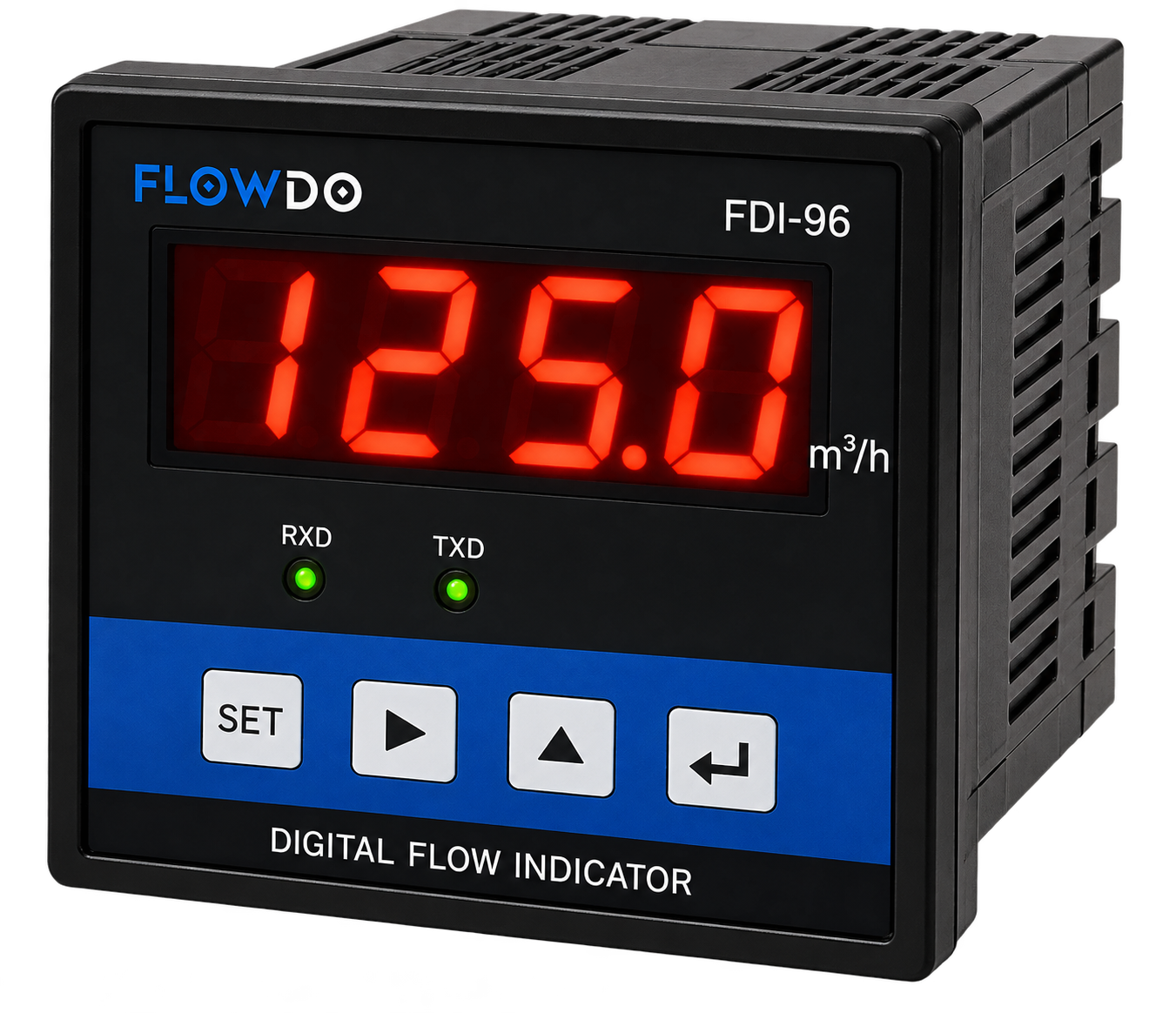
FlowDo FDI-96 Digital Flow Indicator
Other

Digital Flow Indicator

FDI Series Panel-mounted digital process indicator for displaying instantaneous flow rates and totalized volume from compatible 4–20 mA flow meters.

View details & specs →
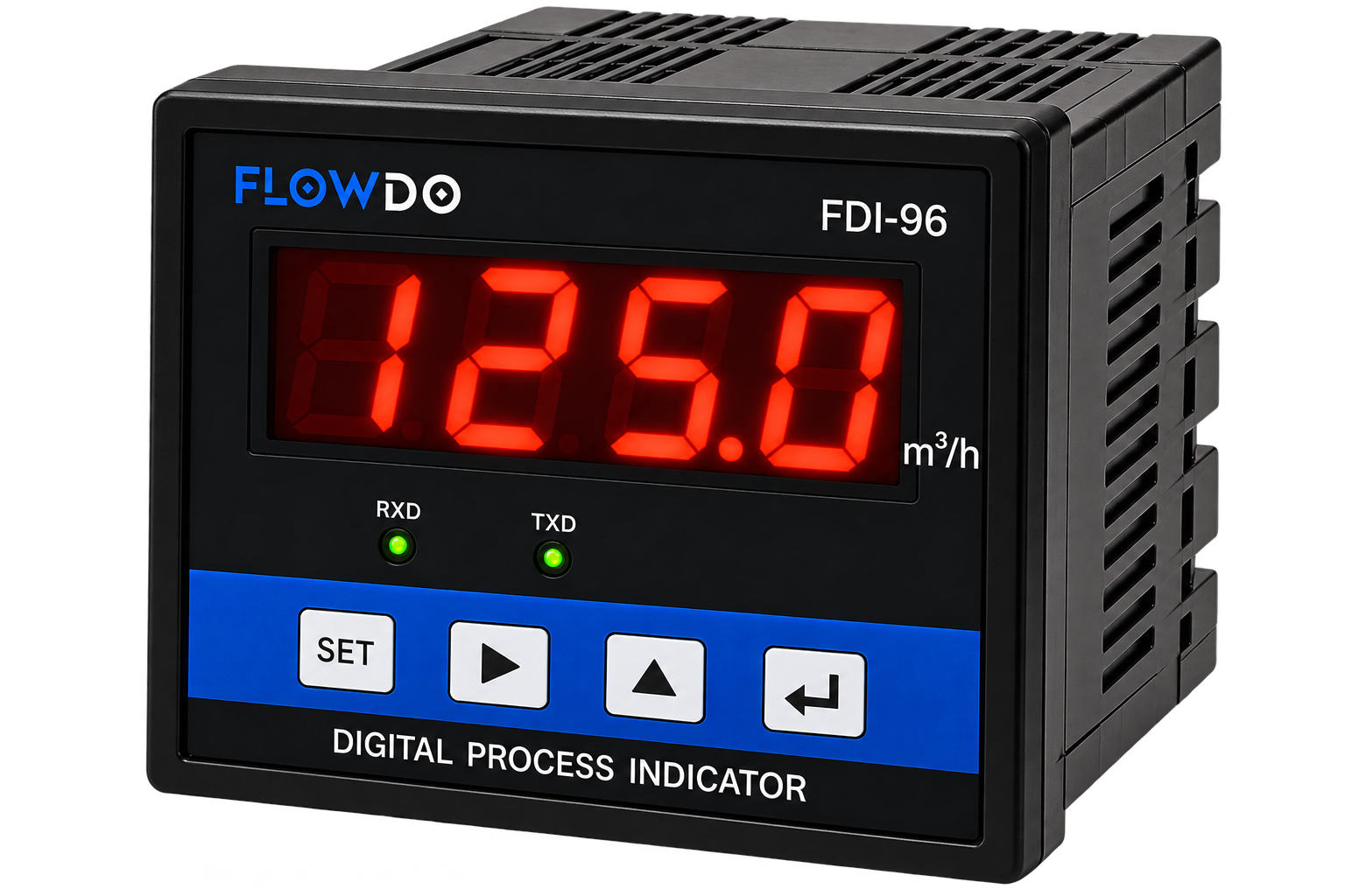
FlowDo Digital Process Indicator
Other

Digital Process Indicator

Programmable panel-mounted indicator for monitoring industrial process variables from standard analog transmitter signals.

View details & specs →
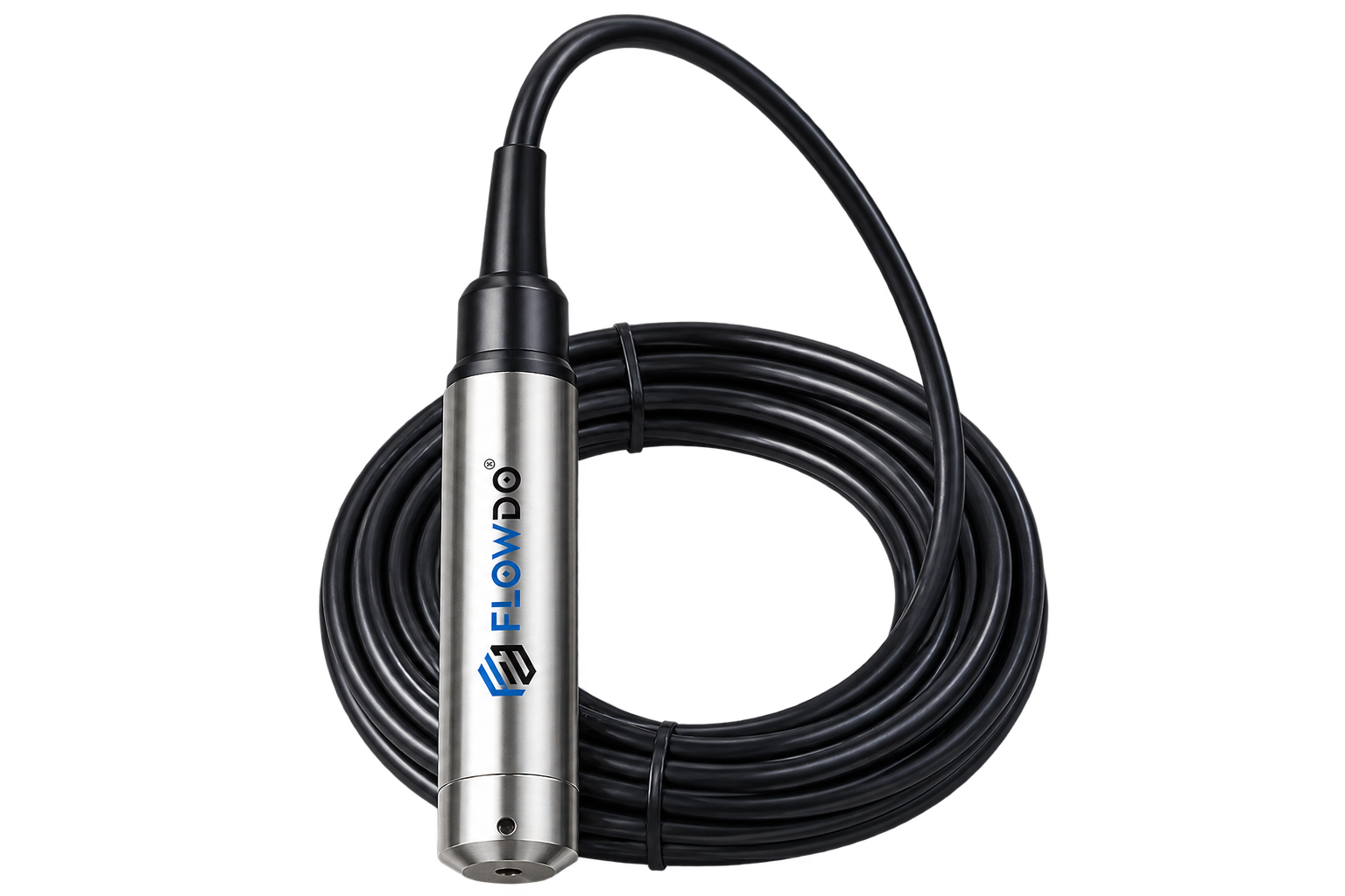
FlowDo FLD-HLT Hydrostatic Level Transmitter
Level Instruments

Hydrostatic Level Transmitter

Model FLD-HLT Submersible hydrostatic level transmitter for liquid-level measurement in storage tanks, reservoirs, and sumps.

View details & specs →
Frequently Asked Questions

Electromagnetic Flow Meter FAQs

Answers to common engineering questions regarding electromagnetic liquid metering.

What is an electromagnetic flow meter?

An electromagnetic flow meter measures the volumetric flow of compatible conductive liquids using electromagnetic induction.

How does it measure flow?

As conductive liquid moves through the meter's magnetic field, an electrical voltage is induced. The electrodes detect this signal, and the transmitter converts it into a corresponding flow value.

Does an electromagnetic flow meter have moving parts?

The electromagnetic measurement principle does not require a mechanical rotor or turbine in the measuring tube.

Can it measure water?

Water applications are commonly compatible with electromagnetic flow measurement when the liquid conductivity and selected meter configuration meet the required specifications.

Can it measure oil?

Many oils are not sufficiently electrically conductive for standard electromagnetic flow measurement. Actual liquid conductivity should be reviewed before selecting the technology.

Can it measure gas or steam?

Standard electromagnetic flow meters are intended for conductive liquids and are not normally used to measure gases or steam.

Why does conductivity matter?

The meter relies on electrical interaction between the moving liquid and measuring electrodes, so the process liquid must have sufficient conductivity for the selected meter.

What liner should I select?

Liner selection depends on chemical compatibility, temperature, abrasion and process conditions. Available liner materials depend on the selected FlowDo model.

Why do electrode materials matter?

The electrodes contact the process liquid and must be compatible with the medium and operating conditions.

Can it provide 4–20mA output?

4–20 mA is standard on supported FlowDo transmitter configurations for interfacing with industrial indicators and control systems.

Does it support RS485 / Modbus?

Digital communication should be listed only where confirmed for the selected FlowDo transmitter configuration.

Does it have a totalizer?

Totalization is presented for configurations where the FlowDo transmitter specification confirms this functionality.

Can it connect to PLC or SCADA?

Yes, when the selected meter output or communication interface is compatible with the PLC/control-system architecture.

Can it connect to FlowDo IoT Cloud?

FlowDo IoT Cloud integration can be configured where a compatible telemetry or interface gateway configuration has been confirmed.

How do I select the correct meter size?

Provide the pipeline size, minimum/normal/maximum flow, process liquid, conductivity, temperature, pressure and connection requirements.

Need Help Selecting a Flow Meter?

Configure the Right Electromagnetic Flow Meter for Your Process

Share your pipe size, flow range, process liquid, conductivity, temperature, pressure, process connection and required output with FlowDo to identify a suitable electromagnetic flow meter configuration.

For faster selection, provide: Pipe Size • Minimum Flow • Normal Flow • Maximum Flow • Process Liquid • Conductivity • Temperature • Pressure • Process Connection • Required Output

Call Get a Quote