
Turbine Measurement
Uses a flow-driven rotor to determine compatible liquid flow with high measurement repeatability.
Responsive Turbine Flow Measurement for Compatible Industrial Liquids
The FlowDo Turbine Flow Meter measures liquid flow using a precision rotor located within the flow path. As the process liquid moves through the meter, the turbine rotates in response to flow velocity, allowing the instrument to determine the corresponding volumetric flow rate.
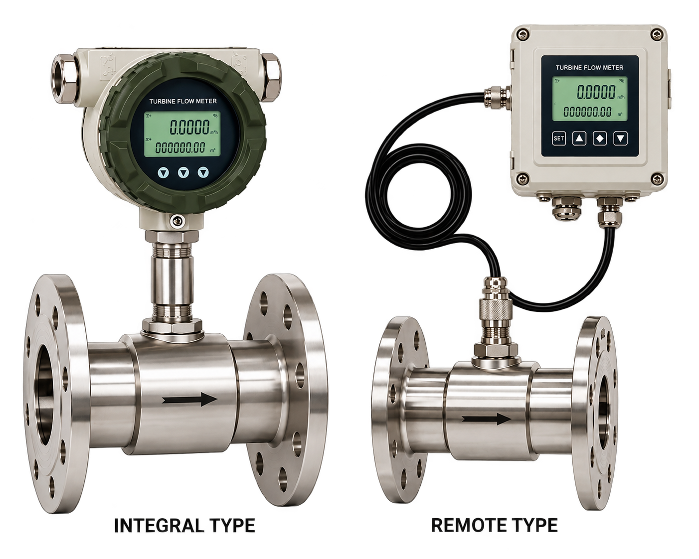
The FlowDo Turbine Flow Meter is designed for volumetric flow measurement of compatible liquids using a flow-driven turbine rotor.
As liquid passes through the meter body, the turbine rotates. Within the meter's intended operating range, rotor speed is related to fluid velocity.
A compatible sensing/pickup system detects the rotor movement and generates a signal that can be used to determine instantaneous flow rate and, where supported, totalized flow.
Engineered for responsive, repeatable volumetric flow measurement in clean industrial liquids.
Uses a flow-driven rotor to determine compatible liquid flow with high measurement repeatability.
Rotor speed changes dynamically in response to flow velocity within the supported operating range.
Applicable meter configurations use calibration/K-factor data to convert sensor pulses into flow information.
Suitable configurations provide a compact inline flow-measurement arrangement for skid and process piping.
Available pickup/transmitter options provide pulse, frequency, or analog signals for indication or automation.
Where supported by connected electronics/transmitter, accumulated volume can be tracked accurately.
Available meter sizes can be selected according to pipeline diameter and expected flow-range requirements.
Designed with robust materials for compatible industrial liquid-flow applications and utility services.
Delivering dependable flow response and straightforward electronic integration.
Mechanical rotor movement responds directly to changing liquid flow within the meter's supported range.
Turbine technology can provide a compact inline flow-measurement solution with high pulse resolution.
Compatible pickup/transmitter configurations provide a usable flow signal for indicators, PLCs, and loggers.
Where supported by associated electronics, pulse information can be used for accumulated-volume measurement.
Different sizes and configurations can be selected according to supported FlowDo options and pipeline needs.
Supported outputs integrate seamlessly with digital indicators, PLCs, SCADA architectures, or telemetry skids.
Comprehensive technical specification architecture for FlowDo Turbine Flow Meters.
For a correctly selected turbine meter operating within its specified range, increasing fluid velocity increases turbine rotational speed.
At low velocities within the linear range, the rotor turns gently, producing fewer pulses per second while preserving proportionality to fluid speed.
As flow velocity increases, fluid forces accelerate the rotor, generating a higher pulse frequency proportional to the increased volumetric displacement.
A turbine flow meter K-factor represents the relationship between sensor pulses and the volume of liquid passing through the meter.
Each time a turbine blade passes the pickup, an electrical pulse is registered. Over a measurement interval, dividing total pulses by the meter's calibrated K-factor yields the exact accumulated volume:
Similarly, pulse frequency (pulses per second) divided by K-factor provides the instantaneous volumetric flow rate.
Turbine flow measurement depends on the relationship between actual fluid flow and the rotor/pickup signal. Factory calibration establishes the specific K-factor for the selected meter.
Key internal and structural components comprising the industrial turbine meter assembly.
Rigid pressure-containing enclosure engineered for inline pipeline installation with minimal fluid disturbance.
Internal flow-conditioning vanes upstream and downstream that condition the velocity profile before it enters the rotor.
Multi-bladed precision rotor hydrodynamically angled to convert flowing fluid velocity into rotational motion.
Axially centered shaft mounted within internal supports to maintain precise rotor alignment in the fluid stream.
Precision bearings supporting smooth, low-friction rotation (ceramic ball bearings available in applicable models).
Detects the passing of each rotor blade and generates an electrical signal according to the selected model.
Threaded or flanged end connections selected according to pipeline specifications and operating pressure ratings.
Clear body markings ensuring the meter is commissioned in the intended hydrodynamic process flow direction.
The turbine rotor and bearing system operate directly within the fluid stream, making fluid conditions critical to performance.
In clean liquids free from suspended solids and fibrous material, the turbine rotor spins freely on its precision bearings, ensuring consistent velocity-to-pulse proportionality.
Liquids carrying sand, scale, fibrous debris, or slurries can cause rotor blockage, excessive bearing friction, or mechanical wear:
Liquid viscosity can influence turbine rotor behavior and the relationship between flow rate and meter output. The selected turbine meter should be suitable for the actual process-fluid viscosity:
Because turbine flow measurement uses moving mechanical components, rotor and bearing condition can influence meter performance over time.
Proper mechanical sizing and piping conditions are critical for stable turbine flow sensing.
Meter selection should consider minimum, normal and maximum process flow rather than pipe size alone, ensuring velocities remain within the linear calibration envelope.
The turbine meter must be installed according to the indicated process-flow direction arrow on the meter body to align correctly with the internal flow-conditioning vanes.
Flow disturbances caused by elbows, valves, pumps or other fittings can influence velocity distribution entering a turbine meter. Follow the straight-run requirements specified for the selected model.
In known industrial turbine installations, recommended straight runs are: 10D upstream and 5D downstream (where D = nominal pipe diameter).
Valves and flow-disturbing throttling components should be positioned according to the installation guidance for the selected turbine meter (typically downstream of the meter).
Rapid pulsation or unstable flow can influence rotor speed and measurement stability. Pump type and pulsation dampers should be evaluated for strongly pulsating lines.
Depending on line size and application needs, different physical mounting approaches may be evaluated.
Meter body installed directly in the pipeline spool with precision internal flow straighteners and full-bore turbine rotor assembly, offering maximum measurement repeatability for standard pipeline sizes.
Sensor installed into a compatible pipeline hot-tap or saddle arrangement. Selection depends on pipe size, installation access, required measurement performance, and application review.
Practical flow measurement across clean water systems, industrial utilities, and compatible fluids.
Flow measurement in compatible clean-water applications, treatment skids, and filtration circuits.
Utility and process-water measurement in plant facilities, boiler feed lines, and closed loops.
Only where meter body/rotor materials, fluid viscosity, and liquid cleanliness are fully compatible.
Flow measurement in compatible fuel, solvent, or light oil lines where supported by model specifications.
Flow monitoring in compatible industrial cooling circuits, chillers, and heat exchange systems.
Compact inline flow monitoring where turbine technology is suited for packaged equipment.
High-resolution pulse output for batch totalization and volumetric dosing where supported.
Flow monitoring in laboratory, component testing, and industrial hydraulic test systems.
General clean industrial liquid flow measurement with compatible indicator and PLC integration.
Evaluating when turbine technology is an ideal fit versus when an alternative flow principle is recommended.
Another flow technology (such as FlowDo Electromagnetic or Ultrasonic Flow Meters) may be more appropriate when process conditions do not suit a mechanical turbine rotor.
Comparing fluid-driven mechanical rotor measurement with electromagnetic induction sensing.
The correct technology depends on the process liquid, conductivity, viscosity, solids content, flow range, required accuracy and installation conditions.
Comparing inline mechanical rotor movement with ultrasonic acoustic wave propagation.
Selection depends on fluid characteristics, pipe configuration, required accuracy, installation access and maintenance considerations.
Understanding when each industrial flow measurement principle is best considered.
No single flow-meter technology is ideal for every application.
Converting rotor movement into pulses, local display, totalization, and plant automation.
Combine high-resolution pulse signals with FlowDo digital indicators for instantaneous flow rates and cumulative volume monitoring.
Provide key parameters to identify the appropriate FlowDo turbine meter model and options.
Nominal pipeline diameter and connection standard.
Minimum, normal, and maximum expected flow rates.
Liquid identity, composition, and cleanliness condition.
Process liquid operating viscosity across temperatures.
Operating and maximum design process temperature and pressure.
Selected according to chemical compatibility requirements.
Threaded (BSP/NPT) or flanged connection standard.
Pulse, frequency, 4–20 mA, or paired digital indicator.
Explore complementary FlowDo instruments that pair with the Turbine Flow Meter.
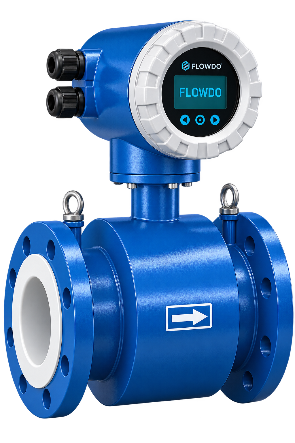
Industrial electromagnetic flow meter for accurate volumetric measurement of conductive liquids with zero moving parts.
View details & specs →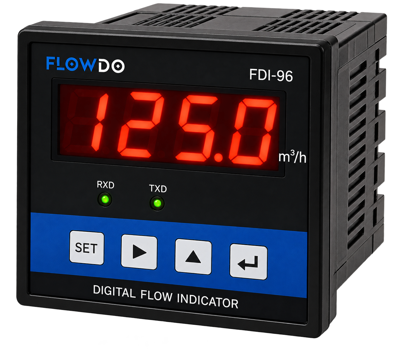
FDI Series High-accuracy panel meter for displaying instantaneous flow rates and totalized volume from compatible pulse and 4–20 mA inputs.
View details & specs →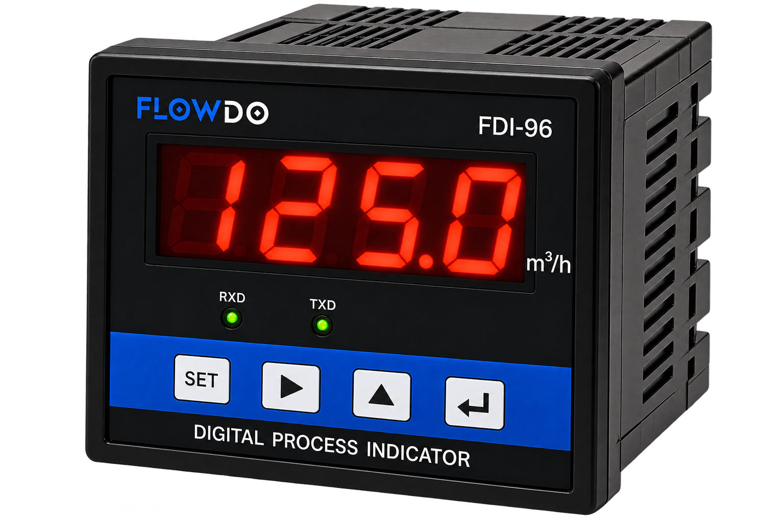
Programmable panel indicator for process monitoring, batch control scaling, and automation integration.
View details & specs →Answers to common technical questions regarding turbine liquid metering and application engineering.
A turbine flow meter uses a rotor positioned in the fluid stream. As liquid flows through the meter, the rotor turns at a speed related to flow velocity.
A pickup/sensor detects rotor movement and produces a signal. The meter's calibration or K-factor defines the relationship between that signal and flow.
K-factor represents the relationship between sensor pulses and a unit volume of liquid for a calibrated turbine flow meter.
Yes. The measurement principle uses a mechanical turbine rotor and associated support/bearing components.
Water can be suitable for turbine measurement when the selected meter's range, material and fluid-condition requirements are satisfied.
Applications containing significant solids, debris or slurry require review because particles can interfere with the turbine rotor and bearings.
Yes. Viscosity can influence rotor behavior and calibration performance, so the selected meter should be suitable for the process fluid.
A turbine meter uses a rotating mechanical rotor, while an electromagnetic meter uses electromagnetic induction and requires a sufficiently conductive liquid.
Pulse/frequency output should only be shown for FlowDo configurations that actually support it.
4–20mA is generally provided through a suitable transmitter/interface where supported. It should only be advertised for confirmed FlowDo configurations.
Yes, where the turbine meter signal is compatible with the selected FlowDo indicator input.
Yes, through a compatible pickup/transmitter/output interface appropriate for the PLC or control system.
Flow disturbances upstream of the turbine can change the velocity profile and influence measurement. Follow the installation requirements for the selected FlowDo meter.
Selection should be based on minimum, normal and maximum process flow along with pipe size and process-liquid characteristics.
Only claim IoT Cloud integration where the turbine signal is connected through a confirmed compatible telemetry/interface configuration.
Share your pipe size, minimum/normal/maximum flow, process liquid, viscosity, temperature, pressure, connection and required output with FlowDo to identify a suitable turbine flow meter configuration.
For faster selection, provide: Pipe Size • Minimum Flow • Normal Flow • Maximum Flow • Process Liquid • Viscosity • Temperature • Pressure • Process Connection • Required Output