
Vortex Shedding Technology
Measures flow using vortices generated by a stationary bluff body inside the pipeline.
Reliable Flow Measurement Using Vortex Shedding Technology
The FlowDo Vortex Flow Meter determines process flow by detecting alternating vortices generated as fluid passes a specially designed bluff body within the measuring section. The resulting vortex frequency is processed by the transmitter to determine the corresponding flow value.
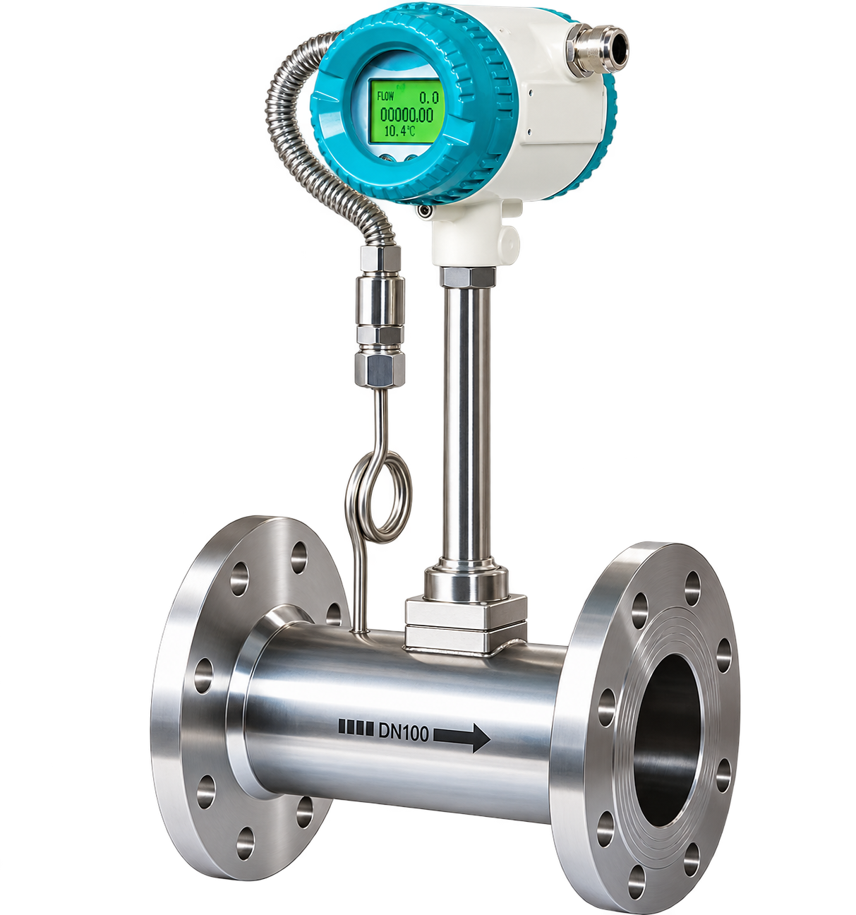
The FlowDo Vortex Flow Meter uses the vortex-shedding principle for industrial process-flow measurement.
Inside the meter, the process fluid passes around a stationary obstruction known as a bluff body. As the fluid moves past this obstruction, alternating vortices form downstream.
Within the applicable operating region, the frequency of these vortices is related to fluid velocity. A sensing system detects the vortex activity, and the transmitter electronics process the signal to determine the corresponding flow value. Unlike turbine flow meters, vortex measurement does not require a rotating turbine rotor.
Engineered for dependable flow sensing across industrial utility and process piping systems.
Measures flow using vortices generated by a stationary bluff body inside the pipeline.
Flow measurement does not depend on a mechanical turbine rotor or moving bearing components.
Provides continuous process-flow information within the supported operating range.
Detected vortex activity is electronically processed into a usable flow value by the transmitter.
Applicable configurations provide local digital indication of momentary rate and volume.
Supported transmitter configurations provide 4–20 mA, pulse, or digital signals for control.
Designed with robust materials for compatible industrial process-flow applications.
Available configurations can be selected according to pipeline standards and pressure classes.
Engineered for dependable industrial service without mechanical wear in the measuring stream.
No rotating turbine measurement element is required, eliminating mechanical rotor wear in compatible media.
Vortex frequency responds directly to fluid velocity within the supported measurement region.
Applicable transmitter configurations provide local digital flow and totalized volume indication.
Supported outputs can transmit flow information directly to plant indicators, PLCs, and control systems.
Vortex technology can be considered for suitable liquid, gas and steam applications depending on model configuration.
Compatible transmitter outputs integrate seamlessly with industrial monitoring and telemetry skids.
Comprehensive technical specification architecture for FlowDo Vortex Flow Meters.
The bluff body is a stationary element positioned in the flow stream. Its geometry creates the alternating vortices required for the vortex-shedding measurement principle.
Unlike a turbine flow meter, vortex measurement does not rely on a rotating rotor to determine flow. The bluff body remains stationary while the sensing system detects vortex activity generated by the moving process fluid.
The selected Vortex Flow Meter uses a sensing system to detect the periodic pressure pulses or micro-deflections created by vortex shedding. The transmitter converts the detected signal into usable flow information.
Vortex shedding operates across diverse fluid states, provided density, velocity, and process parameters meet the selected model criteria.
Vortex technology can be used for compatible liquid applications when the selected meter's flow, density, viscosity, pressure and temperature requirements are satisfied.
Availability depends on selected configuration.Suitable Vortex Flow Meter configurations can be used for compatible gas-flow applications when process conditions meet the selected meter specification.
Availability depends on selected configuration.Vortex flow measurement is commonly considered for suitable steam applications, but the selected meter must be appropriate for the actual steam pressure, temperature and measurement requirement.
Availability depends on selected configuration.Steam metering requirements differ significantly between steam states:
The required measurement architecture depends on whether volumetric flow, compensated flow, mass flow, or energy measurement is required.
Volumetric Flow: Volume passing through the pipeline per unit time (e.g. m³/h, L/min).
Mass Flow: Mass passing through the system per unit time (e.g. kg/h, t/h).
A standard vortex measurement does not automatically mean mass-flow measurement. For compressible media like steam and gas, mass-flow calculation requires density information and appropriate compensation depending on the application and transmitter configuration.
For gases and steam, density varies dynamically with process temperature and line pressure.
In compressible gas and steam lines, fluctuations in operating pressure and temperature alter fluid density. Where compensated mass flow is required, external or supported transmitter inputs incorporate temperature and pressure measurements to compute true dynamic mass or energy flow.
Note: Specific compensation capability depends on the selected FlowDo model and transmitter architecture.Vortex meters require sufficient flow conditions for stable vortex formation and detection. Selection should consider minimum, normal and maximum process flow rather than pipe size alone.
Meter sizing should be based on actual flow velocity across minimum, normal, and maximum conditions to ensure the vortex shedding frequency remains in the linear measurement zone.
Stable vortex measurement requires suitable process velocity. Very low-flow conditions may fall below the reliable vortex-shedding threshold of a selected meter size.
Vortex behavior depends on fluid density ($\rho$), velocity ($v$), characteristic diameter ($D$), and viscosity ($\mu$), governed by Reynolds number ($Re = \frac{\rho v D}{\mu}$).
Elbows, valves, reducers, pumps and other piping components can disturb the velocity profile entering a Vortex Flow Meter. Follow the upstream and downstream straight-run requirements specified for the selected FlowDo model.
Install the meter according to the flow-direction arrow marking on the meter body to ensure fluid impacts the leading face of the bluff body properly.
Because vortex measurement relies on detecting periodic flow pulses, excessive mechanical pipe vibration from nearby pumps or compressors can interfere with sensing. Pipe supports are recommended for vibrating lines.
The bluff body creates a slight obstruction causing a minor pressure drop. Verify that the meter body, sensor materials, and flange connections match the process operating pressure and temperature.
Practical vortex flow measurement across steam distribution, compressed gases, and process liquids.
Boiler header steam distribution and process steam monitoring where selected model is suitable.
Clean utility water, cooling loops, and high-velocity fluid flow measurement.
Compatible low-viscosity liquid measurement free from entrained slurries or large particles.
Plant compressed air generation, audit lines, and distribution networks where supported.
Nitrogen, carbon dioxide, argon, and compatible non-corrosive gas pipelines.
Feedwater lines and energy auditing in central boiler house installations.
Compatible chemical lines where wetted materials and temperature classes match.
Auxiliary steam monitoring, turbine bypass lines, and plant utility management.
District heating steam supply, hot water metering, and central facility utilities.
Evaluating when vortex shedding technology is an ideal fit versus when an alternative flow principle is recommended.
Another flow technology (such as FlowDo Electromagnetic, Turbine, or Ultrasonic Flow Meters) may be more appropriate when process conditions do not suit a stationary bluff body.
Choosing between stationary bluff-body vortex shedding and rotor-based turbine flow measurement.
Comparing vortex shedding with electromagnetic induction sensing.
Technology selection depends on fluid properties, pipe size, flow range, pressure, temperature, installation and required measurement performance.
Comparing inline vortex shedding with ultrasonic acoustic wave propagation.
Understanding when each industrial flow measurement principle is best considered.
No single flow-meter technology is ideal for every application.
Converting periodic vortex frequency into analog signals, totalized volume, and remote telemetry.
Provide key process parameters to identify a suitable FlowDo Vortex Flow Meter configuration.
Liquid, gas, or steam composition and fluid state.
Nominal pipeline diameter and connection standard.
Minimum, normal, and maximum operating flow rates.
Operating and maximum design pressure.
Operating and maximum temperature conditions.
Fluid properties under operating conditions where relevant.
Flanged (ANSI/DIN/JIS) or wafer installation style.
Selected according to chemical compatibility requirements.
4–20 mA, pulse, or digital communication interface.
Volumetric flow vs. temperature/pressure compensated mass flow.
Explore complementary FlowDo flow meters and panel indication instruments.
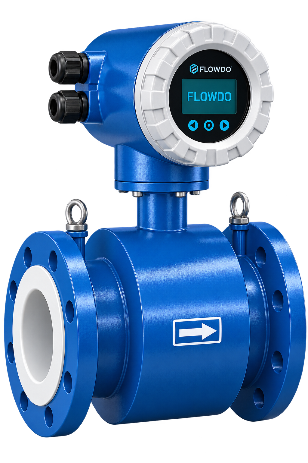
Industrial electromagnetic flow meter for accurate volumetric measurement of conductive liquids with zero moving parts.
View details & specs →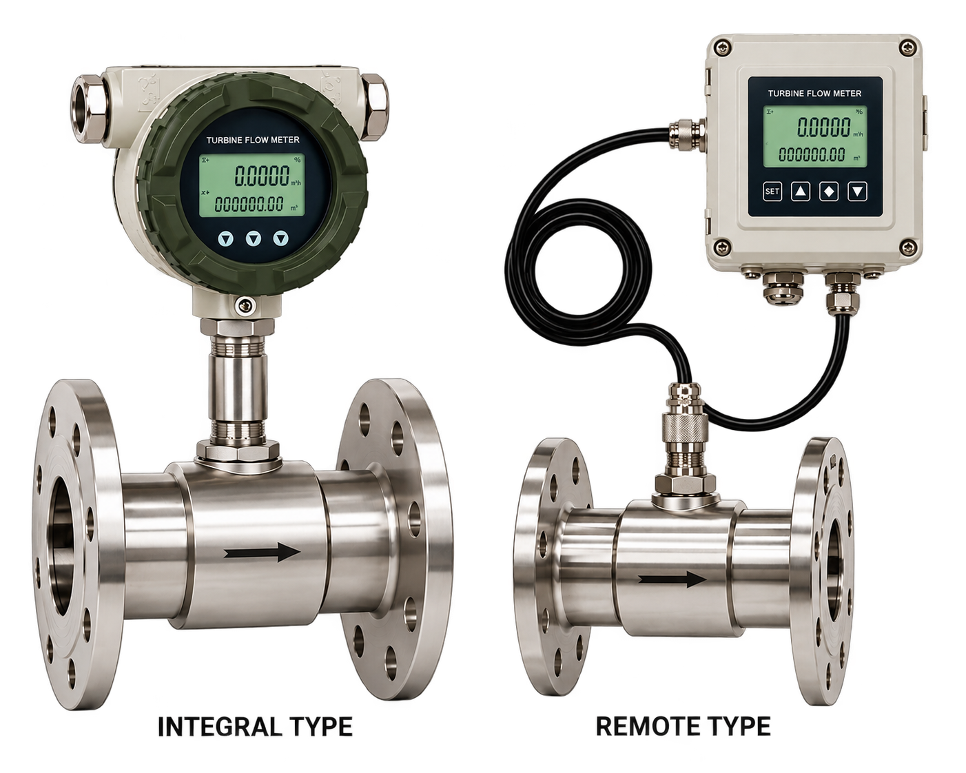
Industrial turbine flow meter for responsive volumetric flow measurement of compatible clean liquids using precision rotor mechanics.
View details & specs →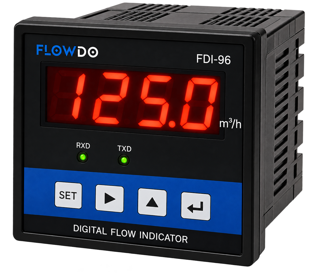
FDI Series High-accuracy panel meter for displaying instantaneous flow rates and totalized volume from compatible pulse and 4–20 mA inputs.
View details & specs →Answers to common technical questions regarding vortex shedding flow measurement.
A Vortex Flow Meter measures flow by detecting alternating vortices generated as process fluid passes a stationary bluff body.
Vortex shedding is the alternating formation of vortices downstream of an obstruction placed in a moving fluid.
It is the repeating pattern of alternating vortices formed downstream of a suitable bluff body.
Within the meter's applicable operating range, vortex frequency is related to fluid velocity. The transmitter processes this detected frequency into a flow value.
No. Vortex measurement uses a stationary bluff body rather than a rotating turbine rotor.
Suitable FlowDo Vortex configurations can be used for compatible liquid applications when the process conditions meet the meter specification.
Gas measurement depends on the selected FlowDo Vortex configuration and process conditions.
Vortex technology is commonly used for suitable steam applications, but steam compatibility and operating limits must be verified for the selected FlowDo model.
Standard vortex measurement does not automatically mean mass-flow measurement. Mass-flow calculation may require density and temperature/pressure compensation depending on the process and transmitter configuration.
Temperature compensation should only be listed where confirmed for the selected FlowDo configuration.
Pressure compensation should only be advertised where confirmed.
4–20 mA should only be shown for configurations confirmed to support it.
Communication protocols should only be shown where confirmed by actual FlowDo technical documentation.
Vortex measurement requires suitable flow conditions for stable vortex formation and detection, so minimum flow is an important meter-selection parameter.
Excessive mechanical vibration can affect vortex detection depending on the meter design and installation.
Upstream flow disturbances can affect the flow profile entering the meter. Follow the straight-run requirements for the selected FlowDo model.
Vortex meters detect vortices created by a stationary bluff body, while turbine meters measure flow using a rotating rotor.
Vortex measurement detects vortex shedding, while electromagnetic meters measure conductive-liquid flow using electromagnetic induction.
Yes, where the selected transmitter output or communication interface is compatible with the control system.
Provide the process medium, pipe size, minimum/normal/maximum flow, pressure, temperature, density/viscosity where relevant, connection and required output.
Share your process medium, pipe size, minimum/normal/maximum flow, pressure, temperature and required output with FlowDo to identify a suitable Vortex Flow Meter configuration.
For faster selection, provide: Process Medium • Pipe Size • Minimum Flow • Normal Flow • Maximum Flow • Process Pressure • Process Temperature • Density / Viscosity if relevant • Process Connection • Required Output • Compensation Requirement